Table of Contents
Introduction
Technical debt is a concept that has gained significant prominence in the software development industry over the past ten years. However the concept was introduced and debated as early as late 2000s. It refers to the cost a software project incurs when developers take shortcuts or make suboptimal design and implementation decisions during the development process. Over time, this debt accumulates, making the codebase increasingly difficult to maintain and extend. This article explores the definition of technical debt, its types, and the best practices for managing and mitigating this risk.
Definition of Technical Debt
Technical debt is akin to financial debt. In the realm of software development, it represents the long-term costs associated with hurried or subpar development decisions. These shortcuts often seem expedient in the short term, allowing developers to meet deadlines or deliver features quickly. However, they typically result in future challenges and increased costs, both in terms of time and resources.
For example, assume you are developing a simple API to serve a mobile application. Your development team has skills in mobile development, and backend development. However, you are lacking DevOps skills in your team.
The CTO is told my the CEO that the deadline to launch the application has moved forward by two weeks because of the client demand. In this situation everyone wants to have a happy customer, therefore, your development team may do a good job in pushing for the deadline, but they have to cut corners as a result. They don’t have enough time to ramp up their DevOps skills and learn how to launch the application with development process in mind. So they rapidly make a container of the backend code, and launch it in AWS ECS.
Notice in this example, we didn’t evaluate how to establish the proper software development lifecycle using unit testing, integration testing, and CI/CD tools. They all leave that behind for the future. For the short term, the launch goes well, but then as customer requests come in, the team cannot rapidly develop.
The development cycle is impacted negatively. They have to go back and do manual testing, and their release cycles fall out of a regular cadence. It will take more time to build features, and this is akin to financial debt. The CTO at some point needs to decide to fix this process because otherwise the prologued impact could be catastrophic to the business.
Ways Technical Debt is Created
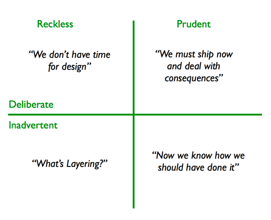
There are different ways technical debt is introduced into software. Steve McConnell in 2007 hypothesized that there are two categories of technical debt: intentional and unintentional. In 2009, Martin Fowler expanded upon it to create the “Technical Debt Quadrant”. This was based on knowing if the debt was deliberate or inadvertent.
Intentional Technical Debt
In the example above, the opportunity cost to not ship the product and miss customer expectation is detrimental to the company’s success, hence in the first iteration the testing and DevOps best practices were ignored. Perhaps in the first few iterations, features could be tested manually, but as the pace picks up, the opportunity cost to not implement DevOps best practices outweighs the benefit.
Developers sometimes decide that the technical debt is worth the risk to launch their software in the market. This is acceptable if the debt is monitored and watched from the time of implementation.
In this case the tech debt needs to be backlogged, tracked and repaid before it becomes burden for the team.
Unintentional Technical Debt
Developers might have designed the software carefully with a lot of thought. However, after implementation and launch, they could realize they could have designed the components of the application better.
This debt comes from bugs and lack of attention or focus from developers. The issues keep adding on.
Accidental Technical Debt
This is where the foundation of software starts off on the wrong path. Imagine developers have to build on a legacy software that nobody is familiar with its codebase. They build upon that broken foundation not knowing the somewhere some poor decision was lead to the poor design. So they have to stop, asses the risk, and track back where the debt started and address it.
Impact of Technical Debt
Prevalence
According to a survey conducted by CAST, a software analytics company, technical debt is present in 76% of software projects. This prevalence underscores the fact that many development teams encounter technical debt at some point in their projects.
Impact on Productivity
The Consortium for IT Software Quality (CISQ) estimated that technical debt can cost an organization up to $1 million per month in lost productivity and rework. And based on the 2022 survey, the cost of poor software quality in the US alone has grown to at least $2.41 trillion. Technical debt is one of the major pillars contributing to this concern. This statistic underscores the severe financial impact of unchecked technical debt.
Maintenance Cost
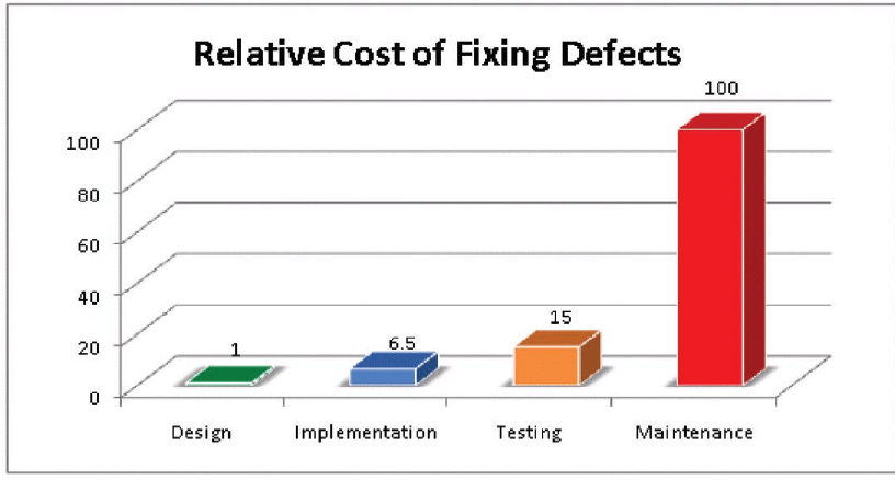
The IBM Systems Sciences Institute found that maintenance accounts for 40-80% of software cost. A significant portion of these costs can be attributed to addressing technical debt.
Types of Technical Debt
Design Debt
This occurs when a software project lacks proper architectural design, resulting in systems that are inflexible, difficult to modify, and prone to errors. Developers must invest substantial effort in re-architecting to address this type of debt.
A prominent example of this is the choice between using a monolithic architecture vs a service oriented architecture. CTOs know that at some point their monolithic application built on a single codebase, is not going to scale with their rapidly growing team size.
In this situation, a decision needs to be made to re-architect the application into separate service all talking to each other via APIs as the contract between them. That way, if team A wants to change a part of the system, the codebase will not be heavily coupled with other parts of the system, and this significantly reduces the risk of errors. Importantly, each team can have their own cadence in developing their services.
For example, AI/ML projects will take more time to accomplish. Assume that you are integrating a generative model into your application support module to aid with customer responses. By the time your AI team has finished their work, the monolithic codebase has evolved so much in other parts, that they would feel they always have to play catchup in keeping their work integrated properly with the rest of the application.
Code Debt
Code debt arises from poorly written, unoptimized, or excessively complex code. It hampers readability, maintainability, and the ability to add new features without causing unintended side effects.
A example of the code debt is when developers don’t use design patterns to address repeatable solution to commonly occurring problems in software design. This causes each developer to maybe unknowingly implement different solutions for the same problem. Recall the good old mantra: “there are more solutions than problems!” This will result in what we know as spaghetti code.
Lets assume there is an common object in your codebase that is used by multiple consumers. As the object evolves based on different consumer needs, the developers likely have to add more class variables, methods, and constructor parameters. But not all consumers use this object the same way. Hence, each developer, creates their own subclass from this object, and overrides the constructor parameters. Although this sounds like a good use case for inheritance, but now we have many children of this object that their sole purpose is to override how this object is built. There are a lot more code to maintain in different files.
This is where a design pattern like Builder comes into play. Its sole purpose is to abstract the way an object is built in an elegant and easy to maintain fashion. So, it is encouraged for developers to master design patterns, and this is why a lot of interview questions cover this topic.
Testing Debt
Inadequate testing or the absence of automated testing can lead to testing debt. This makes it challenging to identify and resolve issues early in the development process, causing defects to accumulate over time.
Take our first example in this article about the mobile app with a backend API. The developers ignored the need for automated testing. This impacted their development cycle speed. It is crucial for any software team to have automated test coverage that can give the team confidence in making changes without having to know all the functionality that might break as a result of their change.
Documentation Debt
Documentation debt occurs when project documentation is insufficient or out of date. This hinders the onboarding of new team members and creates confusion during maintenance and future development.
A lot of us have heard the mantra: “the code is the documentation.” One can assert that their code base is cleanly written, and all object names and variables are meaningful, so it should be easy to understand. However, it is extremely challenging for a new employee to setup their development environment and figure out how services talk to each other without even a bare minimum automated setup script or documentation showing the architecture.
Unfortunately, the examples of this exists in even mature teams where a simple API documentation that can be automatically generated by using tools like Swagger could be non existent.
Dependency Management
Regularly update and manage third-party dependencies to avoid dependency debt. This also helps ensure the security and stability of your software.
Nobody these days writes every single line of code from scratch. There are libraries that are open-source, and make the job of a developer easy. However, developers must be conscious in choosing dependencies for their project that are actively being developed and are not dormant. Otherwise, there could be potential security issues that could be a nightmare to fix if a dependent library is not supported, and you may have to rewrite a significant portion of your application to incorporate a different library or patch and own the existing library.
A rule of thumb is to not use any library that doesn’t have any activity for the past 3 months on its code repository. Except proprietary libraries that should be supported by vendors at all times, this can be examined via Github easily.
Measuring Technical Debt
Now that we have talked heavily about different kinds of technical debt with some examples, it is important to understand how to look at some technical debt metrics.
New Bugs vs. Closed Bugs
Every bug could be accounted toward a tiny technical debt. Software teams need to keep a tally of the number of bugs create vs. the number are bugs that are being closed. If new bugs are outnumbering closed bugs, it is a signal that some changes need to be made.
Code Complexity Metrics
Complex code is an absolute sign of accumulated technical debt. And at some point, someone would need to go an open the can of worms and take on some major refactoring.
There are several factors that go into measuring the complexity of code:
Lines of Code (LOC)
The total number of lines in a codebase. While not a direct measure of technical debt, a large LOC can indicate a more extensive codebase that may have accrued technical debt.
Nesting Depth
Tracks how deeply code structures (loops, conditionals, etc.) are nested. Excessive nesting can make code harder to understand and maintain.
Class Coupling
This measures how many objects in the code are dependent on one another. If too many objects are couples with each other, it would cause changes to be error prone. Best way to address this issue is incorporating proper design patterns and inheritance.
Inheritance Depth
This metrics shows the depth of inheritance of classes. If the depth of inheritance is high, it is likely the sign that lazy approach was applied when developing code, and likely some of the children logic can be implemented in parent classes and a more elegant code can result from incorporating design patterns rather than inheritance each time.
Cyclomatic Complexity
Measures the number of independent paths through the code. Higher complexity may indicate more challenging code to maintain.
There are tools that later we will talk about that would help teams to measure this, but the general rule of thumb is for teams to aim for the lower possible score for each one of these factors.
Code Smells
Qualitative issues in the code that suggest potential problems. Common code smells include duplicated code, long methods, and excessive comments. Tools like SonarQube can help identify code smells.
Code Churn
Code churn is measured by counting the number of times a line of code has been deleted, replaced, or rewritten. The reason this speaks to debt is that if the original design of code was thoughtfully done with reusability and modularity in mind, then it shouldn’t be changed quiet often. Some churn is always inevitable, but after a feature release and bug fixes are done, this metric should be minimized.
If teams see high churn over a long period of time on a particular area of the code, it likely means mistakes were made and quick fixed are being applied.
Test Coverage
This means that how much of your code is being executed when automated tests are ran. This can tell you how efficient the code has been written. When more code is unused, it is likely the sign of a poorly written code. The rule of thumb is to have at least 80% coverage in your automated tests. Anything less than that means that some bugs can arise from lack of enough tests and some changes need to be made.
Static Code Analysis
Each programming language has some lint tools. Tools such as ESLint, TSLint, and PyLint provide insights into code quality, potential issues, and adherence to coding standards.
Regression Rate
Measures how often code changes lead to regression issues, i.e., previously fixed issues reappearing. High regression rates can indicate testing and code quality problems that could be the sign of technical dept.
Code Ownership
As a CTO you want to ensure that your have enough people working on your projects so that if one person is on vacation, and one person gets hit by the bus, you still have a third person to work on the code, otherwise, the show stops here. So having at least three people in a team that work on the same codebase or service is an ideal code ownership.
Perhaps no company every has enough resources to dedicate three people per project, and some people may work on multiple projects. It is not the segregation that matters here, but the average figure across knowledge of the codebase within your team that matters. Otherwise, you cannot delegate property, and we know that having someone unfamiliar with something to do something, it is likely going to result in poor code quality specially without having any of the former contributors around.
Technical Debt Ratio (TDR)
Calculated as the ratio of the estimated effort required to fix the debt to the overall effort invested in the project. The higher the ratio, the greater the technical debt.
(Remediation Cost / Development Cost) x 100 = TDR
Remediation cost can be calculated as a function of the code quality metrics mentioned above.
The effort or development cost is measured by calculating the number of lines of code needs to be written for a product feature, divided by the average resources expended per line.
Development Velocity
This is the time that elapses from the first code commit to a successful deployment. If the time it takes to implement new features is impacted by fixing bug over time, it is likely the sign that quick fixes are being made in each iteration.
Dependency Analysis
Assess the dependency on third-party libraries and components, checking for outdated or vulnerable dependencies. If there are non-addressed issues, then technical depth has accumulated. Nobody likes getting hacked because some package was vulnerable.
Application Performance
If your application or front-end performance is not optimal, it is not a direct sign of technical depth, but it is a warning sign that likely some technologies are outdated or your developers are not paying attention to the performance metrics.
Tools to Measure and Track Technical Debt
So far we talked about what is technical debt and learned about different types of debt and how they are measured with some examples. Now let’s explore the vast majority of modern tools that exist today that you can use to measure and track your technical debt.
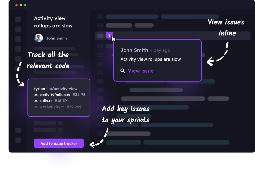
Stepsize
Stepsize is favored by a lot of developers because it seamlessly integrates into the most popular IDE, VSCode. It is designed to help developers identify areas in the code as their are working in their IDE and create issues pertaining the poor design and refactoring and other, from a click of a button inside the IDE. It can practically replace your backlog in issue tracker or even syncs with it and replace documentation in the code to keep it clean. It is free to try for a week but it comes at a price after that.
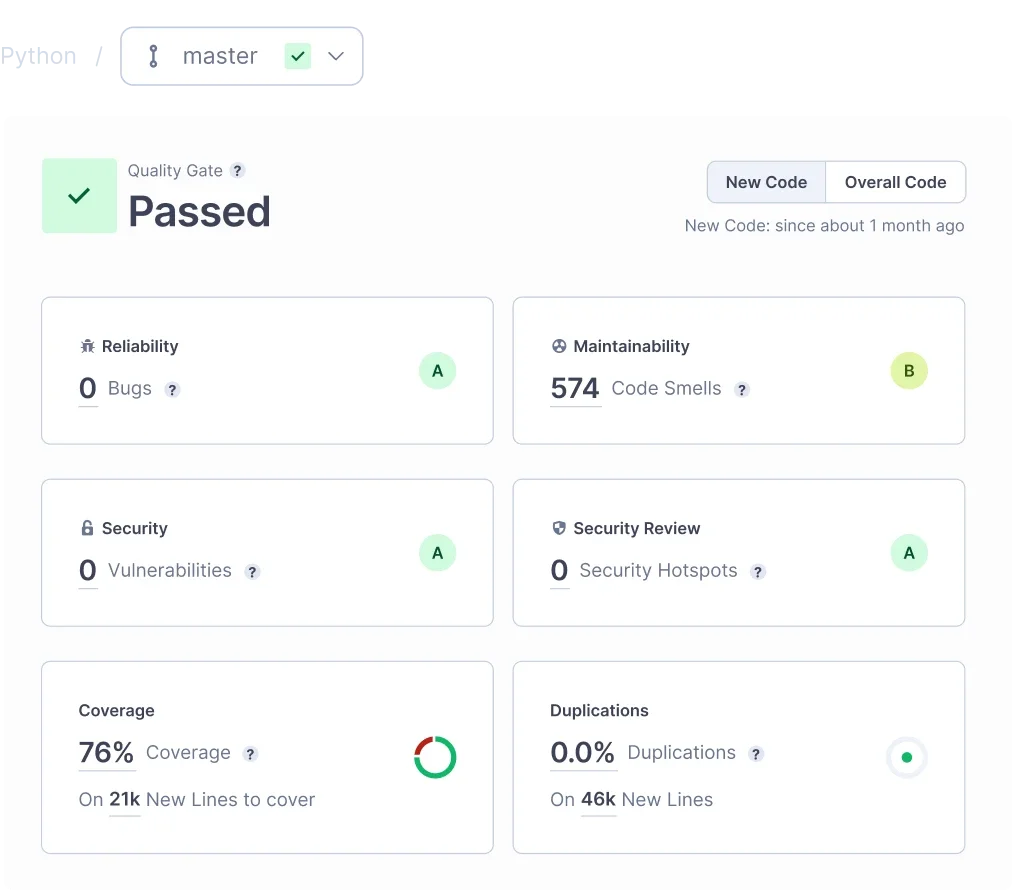
SonarQube
SonarQube is one of my personal favorites from years ago and its purpose is to measure and improve code quality. It highlights potential bugs, code smells, and can also find potential security issues as a result of bad coding practices using static code analysis. It has nice APIs that can seamlessly integrate with many CI/CD platforms so that you can give your developers visibility into their code as part of your development lifecycle. Lastly, it is a known enterprise grade code quality tool that is very well respected as part of any organization seeking compliance as part of their development cycle.
Velocity by CodeClimate
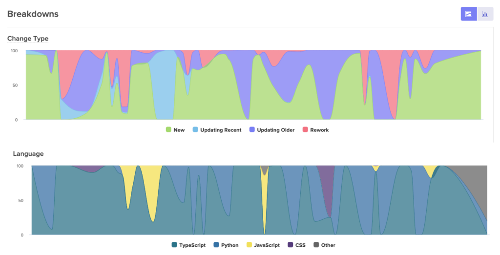
Velocity by CodeClimate seamlessly integrates into your source control like Github and it monitors your development process based on pull requests, issues resolved, code reviews, and how many lines of code have changed. It is the best tool to measure code churn and gage on the quality of the code your team is delivering.
For example the chart bellow shows how much of the code written is new vs. reworked.
Linter Tools
The linter tools are available for almost all programing languages. Checkstyle for Java, PyLint and Flake8 for Python, ESLint for JavaScript and Typescript and CSSLint for CSS. These tools are designed to perform some static code analysis and have robust command line tools that you can use to integrate with Github pre-commit hooks. The advantage of doing it this way is you can create strict coding style and some quality checks provided by these tools right into your code base and prevent developers from being able to commit code without all checks passing. These tools are free.
Dependabot by Github
Dependabot scans your code repositories for outdates package dependancies. This is good for capturing all those package that need upgrading due to security vulnerabilities.
Conclusion
Technical debt is an inevitable part of the software development process, but it is manageable. Recognizing its existence, categorizing it, and implementing effective strategies to address it are essential steps in maintaining a healthy codebase. By proactively managing technical debt, development teams can reduce the long-term costs and risks associated with suboptimal development decisions, ultimately delivering more robust, efficient, and maintainable software products.